Coordinate Tolerancing System
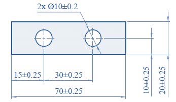
Co-ordinate tolerancing is a dimensioning system where a part feature is located (or defined) by means of rectangular dimensions with given tolerances.
Co-ordinate tolerancing simply does not have the completeness to precisely communicate the part requirements.
Co-ordinate tolerancing consist three major short comings.
• Square or rectangular tolerance zone
• Fixed size tolerance zone
• Ambiguous instructions for inspection.
Square or Rectangular Tolerance Zone
In the above figure the hole location tolerance zone is formed by the maximum and minimum of the vertical and horizontal location dimensions. Due to this a 0.5 square tolerance would be formed. The illogical aspect of a square
tolerance zone is that the hole can be off its nominal location in the diagonal directions, a greater distance than in the vertical and horizontal directions. A more logical and functional approach is to allow the same tolerance for a hole locations in all directions, creating a cylindrical tolerance zone.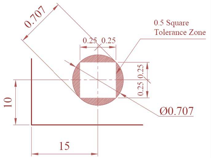
 Fixed Size Tolerance Zone
The print specification requires the center of the hole to be within a 0.5 square tolerance zone whether the hole is at its smallest size limit or its largest size limit. When the important function of the hole is assembly, the location of the hole is most critical when the hole is at its minimum limit of size. If the actual size of the hole is larger than its minimum size limit, its location tolerance can be correspondingly larger without affecting the part function. Square and fixed tolerance zones can cause functional parts to be scrapped. Since coordinate tolerancing does not allow for cylindrical tolerance zones or tolerance zones that increase with the hole size, a lengthy note would have to be added to a drawing to allow for these conditions.
Ambiguous Instructions for Inspections
Coordinate tolerancing results in ambiguous instructions for inspection. The below figure shows two logical methods, an inspector could use to set up the part for inspecting the holes. The inspector could rest the part on the face first, long side second and short side third, or the inspector could rest the part on the face first, the short side second and long
side third.
Because there are different ways to hold the part for inspection, two inspectors could get different measurements from the same part. This can result in two problems: good parts may be rejected, or worse yet, bad parts could be accepted as good parts.
The problem is that drawing does not communicate to the inspector which surfaces should touch the gauging equipment first, second and third. When using coordinate tolerancing, additional notes would be required to communicate this important information to the inspector.


 Launch your Graphy